Viewing your design
This chapter covers the various options for viewing your design.
Elevation
You can elevate all units sitting flush against a wall. If you elevate a wall and units do not appear as you’d expect, check that they are locked against the selected wall. To generate an elevation, first left-click on the wall run you wish to elevate:
Now that you’ve highlighted your chosen wall, click ‘View’ - ‘Elevation’ or alternatively, click on the ‘Elevate’ button.
This will generate an elevation:
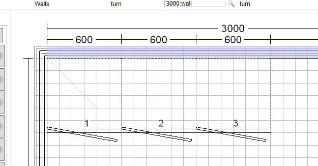
In a wall run made up of multiple wall items (walls including windows/doors/etc), you can only select one at a time. Selecting any of these will elevate the entire wall run.
If you click on ‘Elevate’ as before, this will generate an elevation of the entire wall run:
To change from the default line drawing elevation to a colour render, click ‘View’ - ‘Elevation Options’ or use the drop down menu next to the ‘Elevate’ button - ‘Elevation Options’:
Select ‘Rendered’ in the Elevation options window:
Here, you can also change the settings for including dimensions/labels. Once you’re happy with your options, you can generate an elevation as before:
Bird's-eye View
The bird's-eye view gives you a top-down view of your current design. The view will fit your entire design onto the screen.
You can generate a Bird's-eye view by clicking ‘View’ - ‘3D perspective’ - ‘Bird's-eye view’.

Or alternatively, click on the drop down menu next to the ‘Render’ button and select ‘Bird's-eye’:
This will render a bird's-eye view with the last settings used for a render.
Switching from Line Drawing to Colour Views
There are different options for creating 3D images in ArtiCAD: Line Drawing, Photo-Realism, HD (High-Definition), and Sketch Render. VR (Virtual Reality) is also an available option, where you can move around the design within ArtiCAD.
You can change the style of 3D drawing by selecting ‘View’ - ‘3D options’:
Selecting any of the options will dictate how all rendered views will be generated, except for elevations:
Example of line drawing, photo realism and HD

Back Against Selected Wall
This option generates a view into the room from the middle of the selected wall run.
To do this, select a wall:
Then click ‘View’ - ‘3D Perspective’ - ‘Back Against Selected Wall’:
This will render with the last settings used in ‘3D options…’
Setting Your Camera Position
You can position the camera anywhere within your design by selecting ‘View’ - ‘3D perspective’ - ‘Set position, or clicking on the ‘Camera View’ button in the toolbar:
The Camera
The camera defines which part of your design you wish to view.
The green line on the above image shows the field of view of the camera. Once you have positioned your camera you will see everything above the green line. Everything behind the yellow line is outside your field of view.
If the field of view is outside the room, the 'gap' will be filled with the current sky colour. When positioning the camera, always try and keep the field of view inside the room. This will create a more realistic render.
Summary of controls when positioning your camera
Hold down the left-mouse button to perform the action. Single right-click to cycle through the camera options:
Holding down the ‘Ctrl’ key whilst using any of the keyboard shortcuts, will decrease the amount the camera attribute changes. For example, holding down ‘Ctrl’ and pressing 'a' will rotate the camera in smaller measures than pressing 'a' alone, allowing you a finer degree of control.
Moving the camera
Right-click until the 'Movement' icon appears next to the mouse. Hold down the left mouse button anywhere on the camera and drag it into position, or simply use the arrow keys.
Rotating the camera
The camera rotates about the centre of the front of the camera.
When using the mouse it is best to 'hold' the camera by the point and drag around the point of rotation.
If your mouse pointer crosses the front of the camera whilst rotating it will snap around to face in the opposite direction.
Resizing the Camera
Right-click the mouse until the 'Resize' icon appears next to the mouse. Hold down the left mouse button anywhere on the camera and drag. Move away from the front of the camera to enlarge, or move towards the camera to shrink.
In smaller designs the default size of the camera may be too large to fit inside the design.
Changing the Viewing Angle
Right-click the mouse until the 'Viewing angle' icon appears next to the mouse. Hold down the left mouse button anywhere on the camera and drag. Move away from the front of the camera to reduce the viewing angle, or move towards the front of the camera to increase the viewing angle.
Increasing the viewing angle allows more of the design to be seen in a single image, which is ideal for when working with smaller/more narrow designs. Exaggerating the viewing angle will produce a fish eye effect.
Positioning the Cut Line
Right-click the mouse until the 'Cut line' icon appears next to the mouse. Hold down the left mouse button in front of the camera and drag.
The cut line allows you to remove items from a view that may be blocking your line of sight. Everything in front of the camera but behind the cut line will be removed from the view.

Do not move the cut line too far forward as the camera will extend to either side of the plan
Camera Height and Pitch
The current position and heading of the camera are shown in the top-left corner of the screen. The height is the height of the camera off the floor. The pitch is the angle the camera is 'looking' relative to the horizontal. Increasing the pitch looks 'up' towards the ceiling (a pitch of 90 would be looking straight up). A negative pitch looks 'down' in the direction of the floor (a pitch of -90 would be looking straight down). The pitch can be any value between -90 and 90.
Pressing the "Tab" key will reset the camera back to the defaults:
Once you’re happy with the position of the camera, click ‘OK’ in the top-left corner of the screen to generate the image.
Clicking the ‘Cancel’ button will return you to the design screen.
Clicking the ‘Options’ button will bring up the ‘3D Options’ window.
Storing Your Images for Printing
In order to save an image or use an image on your page layout, you first need to store it. For details of creating a page layout see Creating Page Layouts.
A stored image only exists in the current ArtiCAD session – please note, these images will be lost when you exit unless they are saved.
Select ‘View’ - ‘Store Image’:
Alternatively, click on the ‘Store Image’ button along the toolbar:
A dialog box appears to confirm the image has been stored. Click ‘OK’ to close it:
To see the images you have stored, select ‘Window’ - ‘Browse Images’:
Or, simply click on the ‘Gallery’ button:
The stored images are displayed in a list from left-to-right. The currently selected image has a red outline:
Save: Save the currently selected image. You can specify where to save and the file type (bitmap, JPEG etc).
Save Images: Saves all of the currently stored images. You can specify where to save and the file type. The file name specified will be used for the first stored image (e.g. SmithKitchen.JPG) and any other images will have a number added (e.g. SmithKitchen1.JPG, SmithKitchen2.JPG, SmithKitchen3.JPG).
Delete: Removes the currently selected image from the list. Please note, this does not ask for confirmation.
Delete All: Deletes all the images on the list. You will be asked to confirm.
Load Image: Load in an image from your files.
Slide Show: Displays all the currently stored images in an enlarged window. Use the previous/next buttons to cycle through the images.
Add Drop Shadow: Adds a shadow around the edges of the image.
Seeing Inside Your Units: The following applies to all room systems.
The default setting for ‘Elevation/3D Views’ is ‘Include Unit Doors’, but to see the interior of your units, open ‘Room Settings’ in the drop down menu ‘This Design’:
You will then be able to change the ‘Elevations/3D Views’ to ‘Remove Unit Doors.

Please note, this setting is saved with your design: if ‘Remove Unit Doors’ is selected when you save your design, the doors will still be removed when you next load the design.
Related Articles
Viewing your Design (BathCAD)
This chapter covers the various options for viewing your design. Elevation An elevation view will show you everything touching a selected wall run. Units have to be touching the wall to appear in the elevation. If you elevate a wall and units you ...Viewing your Design (BedCAD)
This chapter covers the various options for viewing your design. Elevation An elevation view will show you everything touching a selected wall run. Units have to be touching the wall to appear in the elevation. If you elevate a wall and units you ...Lighting Your Design (BedCAD)
This chapter will explain how to alter the lighting in your design. Altering the lighting in your design can dramatically improve the finish of your photo-realistic images - the amount of light required will vary from design to design. It is up to ...Lighting Your Design (BathCAD)
This chapter will explain how to alter the lighting in your design. Altering the lighting in your design can dramatically improve the finish of your photo-realistic images - the amount of light required will vary from design to design. It is up to ...Lighting Your Design
This chapter will explain how to alter the lighting in your design. Altering the lighting in your design can dramatically improve the finish of your photo-realistic images - the amount of light required will vary from design to design. It is up to ...